Continuous Toolpath Optimization for Simultaneous Four-Axis Subtractive Manufacturing
Computer Graphics Forum 2024 (Present on Eurographics 2025)
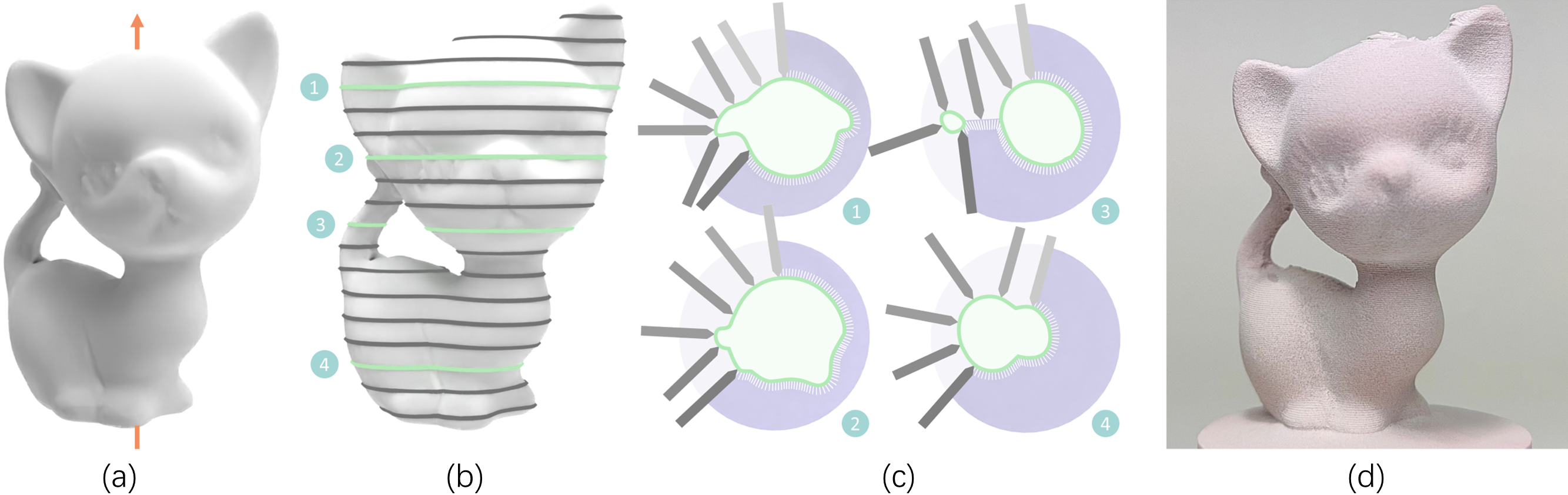
Our algorithmic pipeline in brief. This work introduces a general computational framework for simultaneous four-axis CNC machining, which aims to minimize the variation of tool direction while machining continuously as much as possible, and to ensure that the fabrication process is always collision-free. This figure shows the Kitten model (a). We uniformly slice it along the rotation axis after determining its object orientation (b). Next, we apply tool path optimization to each layer to generate a simultaneous four-axis tool path. This aims to maximize geometric continuity and minimize variations in the machining directions (c). (d) displays the physical fabrication outcome of the Kitten model. It indicates that the proposed framework can be successfully used for simultaneous four-axis subtractive manufacturing.
Abstract
Simultaneous four-axis machining involves a cutter that moves in all degrees of freedom during carving. This strategy provides higher-quality surface finishing compared to positional machining. However, it has not been well-studied in research. In this study, we propose the first end-to-end computational framework to optimize the toolpath for fabricating complex models using simultaneous four-axis subtractive manufacturing. In our technique, we first slice the input 3D model into uniformly distributed 2D layers. For each slicing layer, we perform an accessibility analysis for each intersected contour within this layer. Then, we proceed with over-segmentation and a bottom-up connecting process to generate a minimal number of fabricable segments. Finally, we propose post-processing techniques to further optimize the tool directionand the transfer path between segments. Physical experiments of nine models demonstrate our significant improvements in both fabrication quality and efficiency, compared to the positional strategy and two simultaneous tool paths generated by industry-standard CAM systems.
Fastforward
Algorithm overview
The algorithm introduces a novel end-to-end framework for generating collision-free, four-axis machining paths with both directional and geometric continuity. By adopting a layer-by-layer machining approach, the 3D path problem is simplified into a 2D problem, streamlining the path generation process. The method first slices the target shape into multiple layers of contours, which are then divided into machining primitives. These primitives are merged through a bottom-up process to form continuous machining segments. Graph-cut techniques are employed to remove overlaps between segments, and the Traveling Salesman Problem (TSP) is used to connect the segments, generating the most continuous machining path possible. The final post-processing stage enhances the directional continuity of the path.
More results
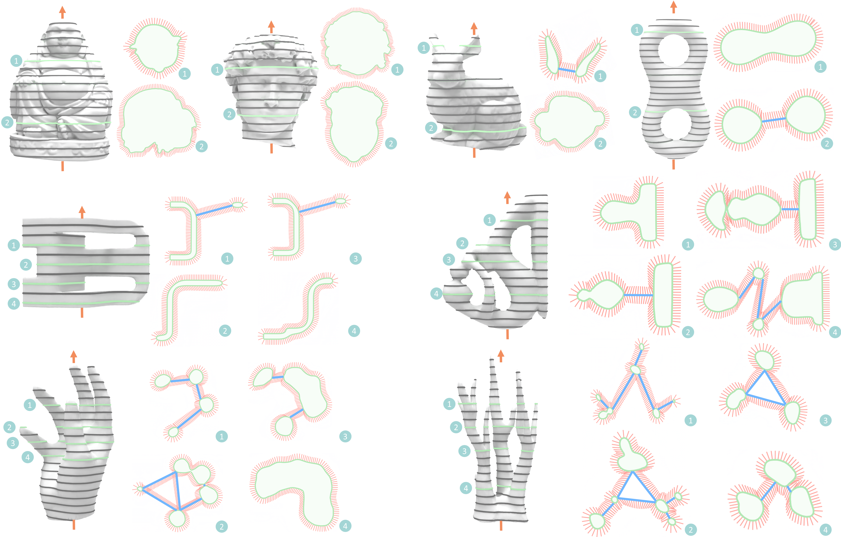
Tool paths results gallery generated by our method. The models are arranged in the order of Buddha, David, Bunny, Eight, Chair, Fertility, Hand, Coral. For each model, we first show the determined orientation of the model and the layer-by-layer slicing, where the two or four layers are picked out and presented. Red lines represent the tool directions of the atomic segments, and blue lines represent the transfer moves between path segments. Note that we apply a larger slicing thickness for visualization, and the intersection of tool directions (red lines) does not imply collisions as the tool moves linearly.
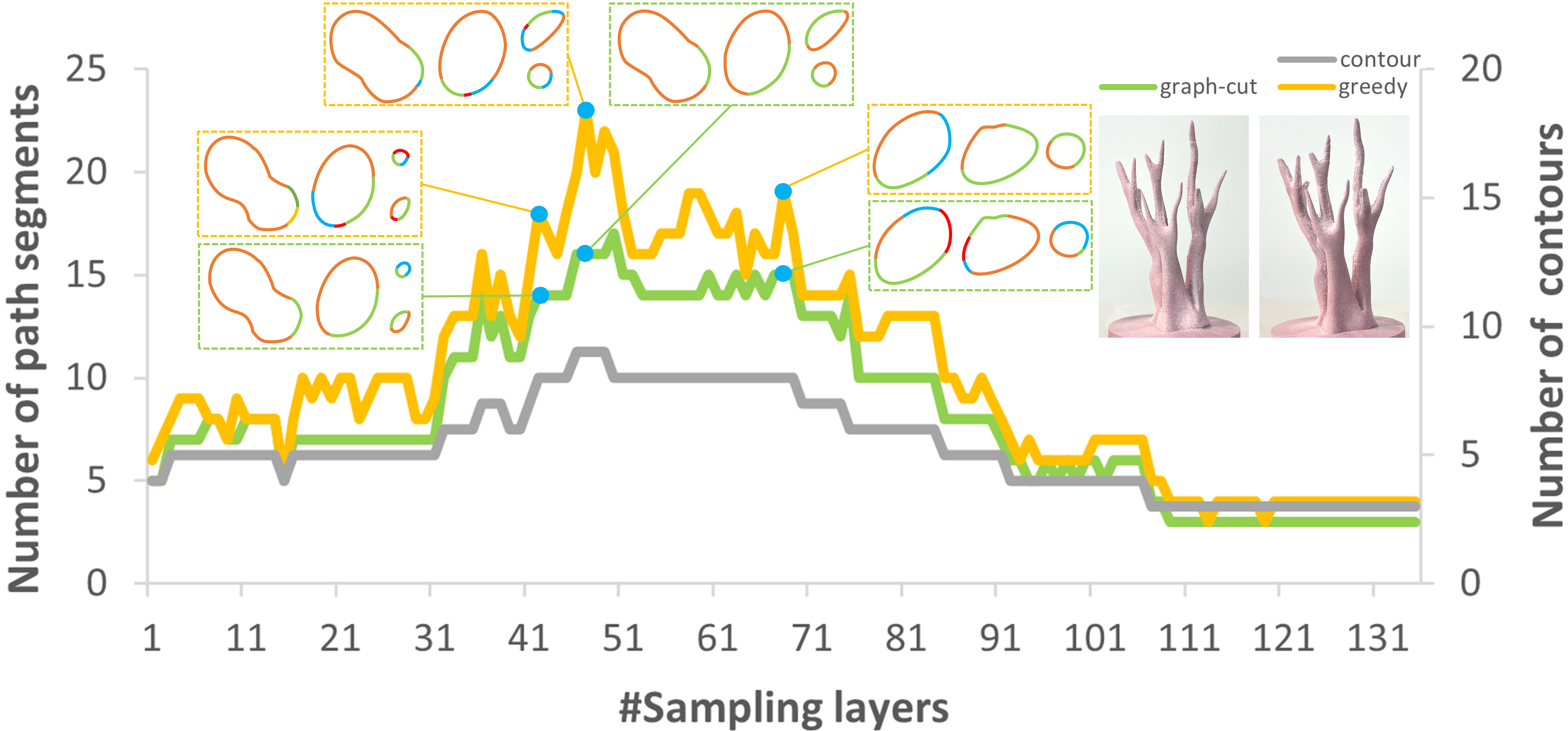
Comparison experiment between graph-cut and greedy method. Comparison between the graph-cut and greedy methods using the Coral model. Graph-cut method (green curve) consistently produces fewer path segments than the greedy method (yellow curve). Additionally, it is observed that the number of path segments produced increases with the number of contours (grey curve). Three layers are selected to demonstrate the path segment decomposition results.
Fabrication results
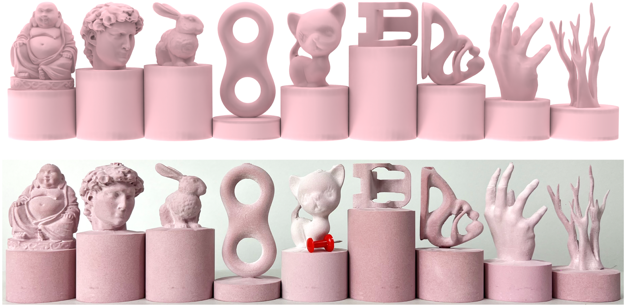
Fabrication results gallery. The upper portion of the figure displays a rendered view of the corresponding input 3D models. The lower portion showcases a collective image of the fabrication results.
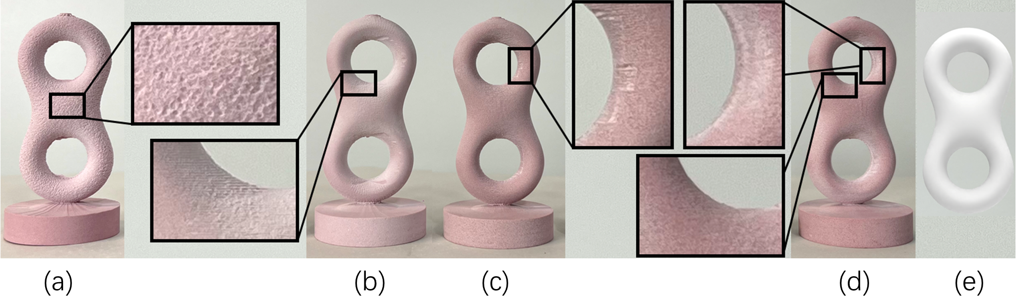
Comparison experiments of post-processing. (a) Fabricated Eight model using the tool path without smoothing of machining directions. The abrupt tool direction transition causes a large number of pits on the surface, which seriously reduce the surface quality. (b) Fabricated results using the heuristic method that first selects the normal direction of each atomic segment, or, if inaccessible, the closest direction within its traverse MDS. The heuristic method makes some overcut artefacts. (c) Fabricated result using the tool path without fine-tuning path segment endpoints. (d) Fabricated result using the tool path with two post-processing strategies. It demonstrates better surface quality. (e) The rendered view of Eight.
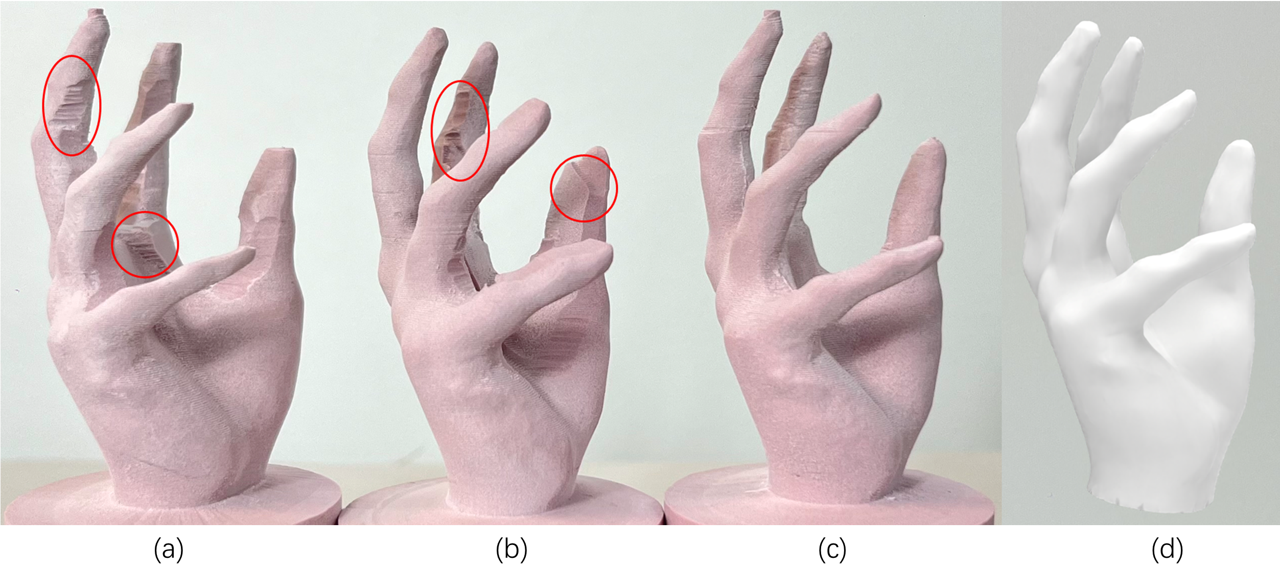
Fabrication results comparison with CAM systems. (a) Fabrication result of the Hand model using the tool paths generated by the Luban CAM software, which takes 115 min for manufacturing. The results exhibit both undercut and over-cut (red circles). The little finger is much thinner than it should be, due to being raised by the overcut. (b) Fabrication result of the Fusion 360 CAM software, which takes 320 min for manufacturing. The results show a lot of undercut, where the palm part is much thicker than it should be. (c) Fabrication result of our method, which takes 80 min for manufacturing. (d) The rendered view of Hand.
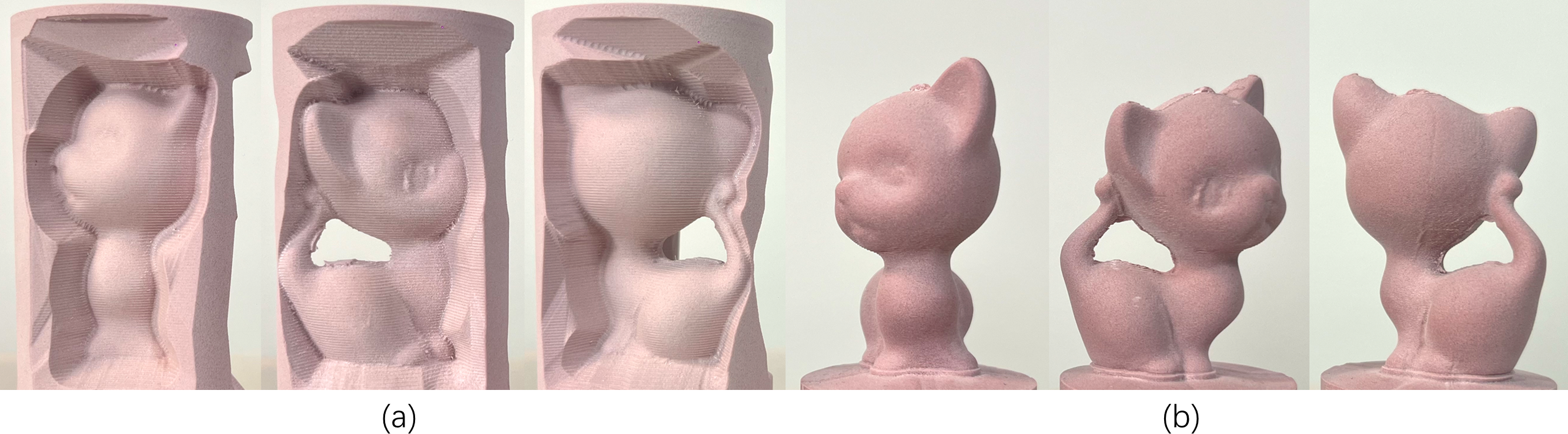
Comparison experiment with positional strategy. (a) is the fabrication result of Nuvoli et al. [NTM*21]. It was machined from three different directions, each producing a height-field patch. (b) is the manufacturing result of our method, as depicted from three different views.
Video
Downloads

Acknowledgement
We thank all reviewers for their valuable comments and constructive suggestions. Thanks for the models provided by Thingiverse and GrabCAD. This work is supported in part by grants from the National Key R&D Programme of China (2022YFB3303200), the National Natural Science Foundation of China (U23A20312) and the Guangdong Basic and Applied Basic Research Foundation (2023B1515120026). The authors thank Zhihao Zhang and Qibing Wu for their practical help with proofreading.